
Building The Source
It’s been a while since my last post, so I thought it prudent to provide a State of the Project update for the Shruthi Clone.
A major breakthrough came in understanding the firmware build chain. Until late last year, the build process yielded a loadable hex file that enabled some functions of the display and LEDs but didn’t result in a fully functional synthesizer.
I experimented with multiple ways to build a hex output, each with varying levels of success. Initially, I was convinced that we had to build in an old Ubuntu virtual machine with the exact GCC version to make everything work. However, after delving deeper into the makefiles sequence and rewriting portions (with the help of my brother Will), I finally managed to generate a load that produced audio and communicated via MIDI!
There are still issues in both the firmware and some of the hardware build (no design issues so far) that we are tracking over on GitHub.
Debugging noisy hardware through firmware understanding
Onto the hardware side of things. This design is susceptible to noise. This concept isn’t surprising in analog electronics, but coupled with firmware that was only “sort of” working, this caused a ton of head-scratching and soldering/desoldering before I discovered the real issue.
What brought the debugging process to a crawl was “noise” ( in truth it was signal bleed) from the analog pots (potentiometer encoders). These pots are on the digital board and are intended to control everything about the synthesizer’s oscillators, filters, sequencer, LFO, and everything else. For the majority of the time working with the first three prototypes, these were useless.
The synthesizers display indicated random settings (for instance, the analog filter cutoff) were constantly changing when none of the actual knobs were manipulated by hand. So, consulting back to the original design build instructions (Here), Pinchettes called this phenomenon “moved by a ghostly hand,” which I really love.
Now, onto the code. The source code includes a nice function here that caused a kind of feedback loop in our debugging efforts:
pots_multiplexor_address =0;
adc_warm_up_cycles_ = 8;
adc_hot_address_ = 0;
adc_resume_scan_to_ = 0;


void Ui::ScanPotentiometers() {
  adc_.Wait();
  uint8_t address = pots_multiplexer_address_;
  uint8_t physical_address = address;
  int16_t value = adc_.ReadOut();

    *PortA::Mode::ptr() = 0xfe;
    pots_multiplexer_address_ = (pots_multiplexer_address_ + 1) & 31;
    if (adc_resume_scan_to_ == 0) {
      adc_resume_scan_to_ = pots_multiplexer_address_ + 1;
      pots_multiplexer_address_ = adc_hot_address_;
    } else {
      pots_multiplexer_address_ = adc_resume_scan_to_ - 1;
      adc_resume_scan_to_ = 0;
    }
/*-------
The ADC conversion is run on the particular Pot now that the mux is set up
--------------*/
      int16_t previous_value = adc_values_[address];
      int16_t delta = value - previous_value;
      int16_t threshold = adc_thresholds_[address];
      if (delta > threshold || delta < -threshold) {
        adc_hot_address_ = physical_address;
        adc_thresholds_[address] = kAdcThresholdUnlocked;
        queue_.AddEvent(CONTROL_POT, address, value >> 3);
        adc_values_[address] = value;
      }
    }
The code drives the rate at which the multiplexors on the boards are scanned at. Lets walk through it:
Case 1: adc_resume_scan_to == 0.
The adc hot address is loaded to the pots_multiplexor address and the conversion just proceeds
Case 2: adc_resume_scan_to =/ 0
The current value of the mux address is read again it appears and then the resume_scan is pushed back to 0.
Now working our way down, where does adc_hot_address_ get initalized? That is a copy of the inital pots_multiplexor_address that started the entire operation. There also are some “warm up” conversions to the pots which I presume are related to the settling time of the multiplexor before valid voltages are present. You can see the threshold here establishing the adding a new event and pushing the hot address now back to the physical address that started up the operation.
At a higher level, this means that when the firmware notes a change in the last Voltage read from a given potentiometer, the rate at which that signal will be sampled will go up. This means that a faulty pot that may not be emitting a DC level will get sampled much more.
This deep dive came after noting that I was observing the multiplexer rate changing based on the current positions of certain pots. A potentiometer would have signal bleed through when it was sampled and would show a what looked like a spike, which i presume was an effect from switching another pot to the problematic pot. The firmware (as noted above) was looking for changes that would exceed this adc threshold setting and once that happened a given mux setting would be sampled more often and the loop would continue. Apologies on the seemingly repetitive nature of this section, but the debugging indeed went in these circles for a while before I developed an idea of what was going on and then looking into the firmware.
Ultimately, the solution was to remove the problematic pot but not leave the signal floating (an open signal drove the same quick sampling behavior), but terminate the removed pots traces to ground. Once I understood this failure mode of the system, I could move further to review of how the actual analog section was working.
Analog Output Exploration
Once the two analog boards were generating some audio, I took some baseline scope shots of the analog output Voltage. Waveforms from the analog out at various synthesizer presets are captured below. Note the “hash” on these waveforms is the PWM (Pulse Width Modulated) signal present in the output. The theory is that once you run the audio through another system that signal should get wiped down. I’m debating whether I want some outboard filtering in addition at some point, but that would be a whole feature.
Basic

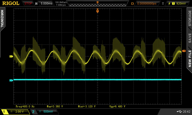
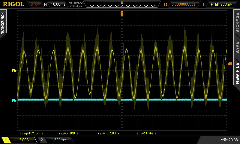
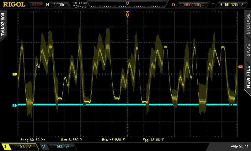
I am not sure if the outputs here match whats intended but Its definitely audio waveforms that make some sense with the patch names!
Building more Samples
Many of the related headaches that I encountered had to do with the build. It took a very long time to establish a baseline performance on either prototype, and the original digital control board is now all but useless. The two issues mentioned above were only possible to solve by building fresh digital and analog boards and comparing the differences between them. This classic “two prototype” issue always arises in hardware development. The more prototypes you develop the more you can compare their behavior instead of go right to theoretical failure modes. I spent a long time just with one build and that slowed me down a good deal.
Once I had a good grasp of how the firmware operates and how to successfully load working code, I went back and built another analog board to run two synths simultaneously. Even that alone has sped up my workflow and debugging. Ultimately, it revealed that my first build of the analog board had far more issues than I originally thought. As of today, we have two sets of hardware that perform (almost) the same.
Path forward
I have started tracking issues on GitHub here.
Next major step is to build at three more prototypes of the synth before I call it a day on this project and decide where it goes next. I have already noted that obsolete parts, like DIP ICs again, are cropping up on this design as I go back to Digikey. A decision will have to be made on how much I want to invest in this project long term, but I have at least three friends who need final products (or, at best, working prototypes).
I still haven’t gone into the enclosure design for the product, but that needs to be done before these last three are totally finished.
A third part will be reviewing pricing and cost of the whole project. This wasn’t done for free and I just want to review where the money went even on something as simple as a rebuild of an existing design.
This blog will continue to serve for these sorts of snapshot updates on the design, although I’m considering using the GitHub wiki to log the design changes or modifications for the future… who knows. What should appear on the blog is a summary and description of the price of all these parts, even with my steps/missteps along the way.
Thanks to my brother Will for the assistance on all of this. There’s no way I could have navigated the makefile and git conflicts as quickly without his help.
