
July 2023 Update (5ish months in)

Its hard to believe how much (or how little) can happen in five months. So I wanted to do an update on where I’ve gotten to on this Shruthi synthesizer project since February. At this point I expected to be wrapped and building units two and three, but things rarely go so close to plan.
So far this project has tackled:
- PWB design
- Analog electronic analysis
- Source control and Git when working in an emulated version of Ubuntu
- My very rusty soldering skills
- Reading someone else’s micro controller code
- Emulating old versions of Ubuntu to get GCC to compile correctly.
- Logistics on buying parts and when in 2023 you can and cant get them.
- How to keep sane when you cant fit all of your equipment in your apartment.
- How to manage workflow going between a lab in your parents basement and your own place.
- Time management around this hobby project, personal crises and relationships, and the day job.
But the biggest realization is running this sort of project for me is that I need a better system for this sort of work. That system should be easy to make a habit out of.
The plan was to make very clean summary blog posts of each phase as i went through the project. The second post on buying the components and the PWB has been in draft for quite some time now even though there are many words written. There’s nothing that is inherently problematic about that post, its just that formalizing it and feeling “comfortable” releasing that article is entirely independent from where I’m at in the project today.
Today I’m looking at the two Highest bits of parallel data signals toggling to the OLED display and they are active and look to be reasonable transition times!
But when I inspect the front display there is no active OLED display activity…..
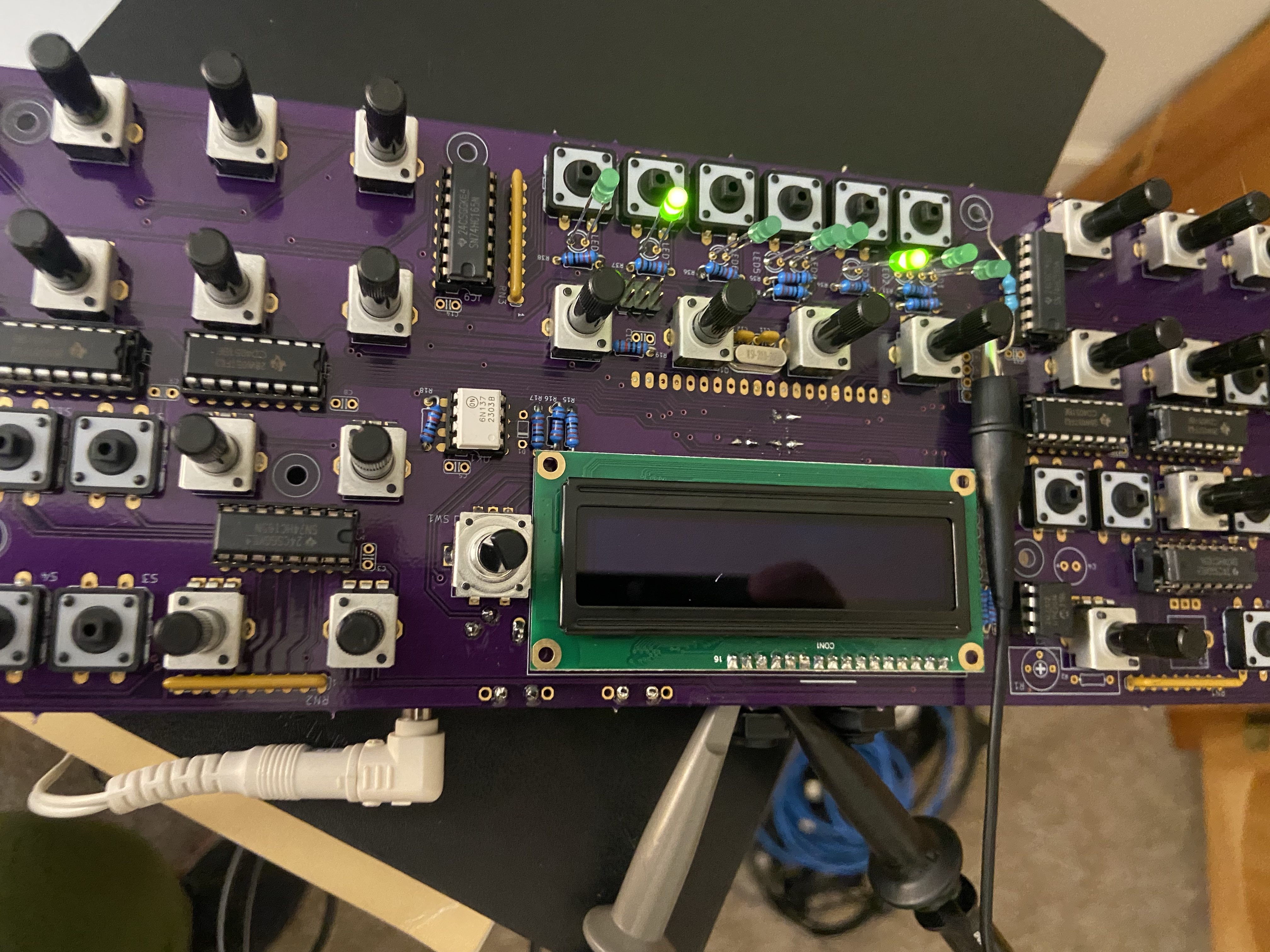
👎👎👎👎
I’ve built two prototypes (this one performing better than the first one I butchered with some trace destruction. So now I’m grappling with a few other ideas Id like to explore more as this project moves forward.
How to synchronize work across multiple computers
This has been easily the slowest process. I could have kept it basic and done a google drive of everything months ago but I insisted on using Git to its full intent and not what works for me. I’m glad for the experience but more calories have been spent in pulling my Digikey order googling the the same datasheet on multiple machines that I’d like to mention.
Other options are out there I’m sure and Git should work I think too but deciding on this is a task in itself that gets me away from the hardware.
How to prioritize work
I had an instinct this was going to happen but it was only magnified with personal issues with my family over the time I had to tend to. Quick takeaway is that this project needs space in my week without the consideration of what I’m going to do once I get there. Preparing for the next week may be a better matter of keeping documentation organized and available to jump in no matter what location
How to keep the right tools available
I bought quite a few things so far on this project that haven’t gone into the hardware. Flux, Solder Iron tips, a new drafting chair after my back was hurting, magnifier glasses. But I’ve also made the mistake of taking have soldered assemblies back to my apartment with my o scope and needing either a 9V adapter or a DMM i didn’t bring back. Maybe the solution here is to have a semi “mobile” lab setup if I’m going to do certain tasks in one place as opposed to another, and just pack it up each time.
How to get a more systematic hardware bring up plan.
On the last one I think I couldn’t have known that ahead of what I experienced.
How can this be so? The display gets a clearly intentional signals from the micro (pins are wiggling correctly) but it does nothing to drive the display with anything meaningful. Could this be a pin assignment issue?

Schematics indicate the same pins are used to connect to this Display. The other oddity is that the control pins look deliberately controlled. Pin 5 (R/W MPU Read/Write select signal, R/W=1: Read; R/W: =0: Write) stays Low. Pin 6 (E MPU Operation enable signal. Falling edge triggered) always high. Since I didn’t write this code I’m not sure how the firmware could screw this up in this partial manner. Could a transfer to the device really be occurring that would have some pins activate and others stay high???
